Archive for the 'Macintosh Floppy Emu' Category
400K Floppy Support
I’ve added 400K floppy support to Floppy Emu, so now you can boot up System 1.1. The fix took all of fives minutes, so why didn’t I do this ages ago? Grab the latest Floppy Emu file archive for the new software.
2 commentsFloppy Emu Disk Menu
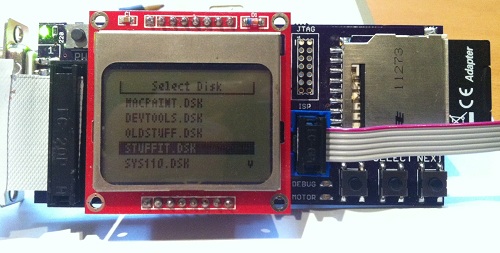
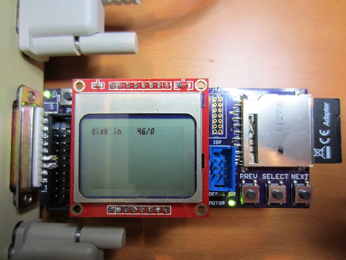
I finally got around to building a proper floppy disk image selection menu. Instead of loading a hard-coded rfloppy.dsk disk image file from the SD card, Floppy Emu now scans the SD card for all files with a .dsk extension, and displays a menu of available disk image files. The PREV/NEXT buttons navigate the menu, and the SELECT button inserts the selected disk image into the virtual floppy drive.
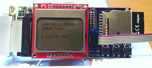
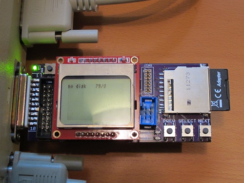
When a disk image is inserted, the LCD displays the name of the Macintosh volume that’s inside the disk image – “System Tools” in the example above. It also shows the current track and side being accessed. For write operations, the LCD displays the track, side, and sector that was written, as well as the time required for the write.
Download the Floppy Emu file archive for the new firmware.
No comments
Build Your Own Floppy Emu
Over the past several months, many people have written to me about the Macintosh Floppy Emu, asking if they could buy one, or when the project would be finished. Since I haven’t made any progress on Floppy Emu in ages, I’m doing the next best thing and releasing the design files and build instructions to the community. If you’re skilled with a soldering iron and embedded development tools, you can use these to build your own Floppy Emu, or improve upon its design.
Warning! Building a Floppy Emu requires advanced soldering skills. Almost all the parts are surface mounted, and there are several SMD chips with fine-pitch 0.5 mm pin spacing. These can be soldered by hand, but it’s tedious, error-prone work. If you’ve never done this type of soldering before, think hard before starting this project. Now with that out of the way, let’s get started!
Download the Floppy Emu design file archive
What You’ll Need
- A Windows PC
- AVR Studio 5 software from Atmel. This is free software. AVR Studio 6 probably works too, but I haven’t tried it. AVRDUDE should work as well.
- An AVR programmer, such as the AVRISP mkII
- A high-speed class 10 SD or SDHC card
- Soldering iron
- Patience
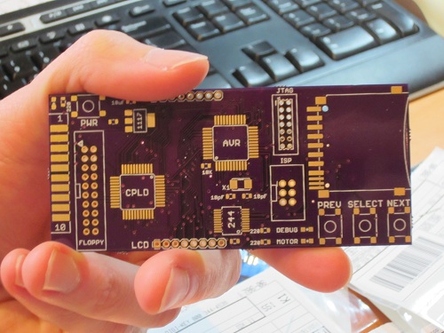
Making a PCB
To begin building your Floppy Emu, you’ll need a printed circuit board. There are many on-line services that will make these for you, using a set of layout files called Gerbers. You will find the Floppy Emu Gerbers in the file archive, in the directory eagle\floppyemu\gerbers.zip. I recommend using the Dorkbot PDX PCB Order service to get the PCB manufactured. Send them the Gerber files, and they’ll make three copies of the PCB for about $30, with a turn-around time of a few weeks. The guy who runs the PCB service is very helpful if you have questions.
Getting the Parts
While you’re waiting for the PCB to be manufactured, you can locate all the other parts you’ll need to assemble the Floppy Emu. You’ll find a complete parts list in the file archive. The total parts cost should be about $40, which is dominated by the AVR microcontroller and the Xilinx CPLD.
One of the required parts is a male DB-19 connector, which mates with the Mac’s external floppy port. These can be very difficult to find, and IEC is the only supplier I know that has them. If you can’t find a DB-19 solder type connector, you can still use the Floppy Emu with its alternate IDC20 connector, which is readily available from electronics suppliers. With the IDC20, there are several different connection options:
- Connect the IDC20 to the internal floppy connector inside your Mac (you will need an IDC20 cable)
- Connect the IDC20 to the circuitry inside a real external Apple floppy drive enclosure, after removing the drive guts
- Use an Apple II DB-19 to IDC20 cable
If you don’t already have them, you’ll also need a high speed class 10 SD or SDHC card, and an AVR programmer like the AVRISP mkII.
Assembly
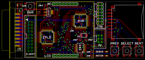
Here’s where things get fun! Refer to the file floppy-emu-layout.png for placement information, or check the schematics.
The first step is to solder and test the AVR.
- Solder the AVR. Pay attention to the orientation – the dot in the corner of the chip should match the dot on the silkscreen. I recommend using the drag solder technique. Begin by soldering two pins on opposite corners of the chip to tack it in place. Verify that the pins are perfectly aligned with the pads on the board before proceeding. Now goob an absurd amount of solder onto the remaining pins. You will probably bridge most of the pins together – that’s OK. Finally, go back with a solder wick and flux, and wick away all the excess solder. Surface tension will hold the solder onto the pins and pads where it belongs, while the excess is magically wicked away. Use a 10x jeweler’s loupe to visually inspect the pins for tiny bridges or gaps.
- Solder the crystal, the 18pF capacitors C12-C13, the AVR decoupling capacitors C4-C7 (these are on the back of the board), the voltage regulator, and the regulator capacitors C10-C11. Also solder the DB-19 connector. It fits along the edge of the board, with the thickness of the board fitting between the two rows of solder cups.
The AVR microcontroller should now be functional. You can use AVR Studio to test it out.
- Install the AVR Studio 5 software on your PC and run it.
- Connect the Floppy Emu board to your Mac, and turn on the Mac.
- Connect the AVRISP mkII programmer to your PC.
- Press the ISP connector into the board, but do not solder it yet. If it is soldered too soon, it will be in the way of your iron later.
- Connect the AVRISP’s programming cable to the ISP connector on the board.
- Click on the AVR Programming button in the toolbar. It looks like a chip with a lightning bolt.
- In the programming dialog, set Tool to AVRISP mkII, Device to ATmega1284P, and Interface to ISP
- Click the Apply button
- Where it says Device ID at the top, click the Read button. Push the ISP connector firmly sideways while you do this, to ensure its pins make electrical contact with the board.
If everything is working, the Device ID field should now display 0x1E 0×97 0×05. If it does not, or you encounter an error, review the steps above, then go back and carefully re-check all the solder connections. Do not proceed further until you are able to retrieve the AVR device ID.
The next step is to program the AVR with the Floppy Emu software.
- Open the AVR Programming dialog again.
- From the list at the left, click Fuses to display fuse information.
- Set the fuses:
- BODLEVEL – disabled
- OCDEN – off
- JTAGEN – off
- SPIEN – on
- WDTON – off
- EESAVE – off
- BOOTSZ – 4096W_F000
- BOOTRST – off
- CKDIV8 – off
- CKOUT – on
- SUT_CKSEL – EXTXOSC_8MHz_XX_16KCK_65MS
- Click the Program button in the fuse panel. Push against the ISP connector with your finger while you do this.
- From the list at the left, click on Memories to display AVR memory information
- Under Flash, verify that “Erase device before programming” is checked
- For the Flash filename, choose AVR\release\floppyemu.hex from the file archive
- Under Flash, click the Program button. Push against the ISP connector with your finger while you do this.
- Remove the ISP connector from the board.
Congratulations, the AVR setup is now complete! The next step is the Nokia LCD.
- Solder the level converter (the 74LVC244), its decoupling capacitor C8, and the 10K resistor R4.
- Solder the two 8-pin male 0.1 inch headers to the Nokia LCD.
- Solder the top 8-pin female 0.1 inch header to the board. Place the bottom header in the board, but do not solder it yet.
- Connect the LCD to the Floppy Emu board. The thicker part of the LCD bezel should be at the top.
The LCD should now be functional. Connect the Floppy Emu to your Mac, and turn the Mac on. If everything is working, the LCD should show “SD Card init error”.
The SD card reader is next.
- Solder the SD connector, and its decoupling capacitor C9.
- Insert the SD card into your PC.
- Format the SD card as a FAT32 disk.
- Copy all the files from the SD files directory in the file archive onto the SD card. Don’t copy the directory itself, only the files that are in it.
- Put the SD card into the Floppy Emu.
Connect the Floppy Emu to you Mac, and turn the Mac on. If everything is working, the LCD should show “no disk 79/0″.
The final assembly step is the CPLD.
- Solder the CPLD. Pay attention to the orientation – the dot in the corner of the chip should match the dot on the silkscreen. Use the same technique for soldering the CPLD that you used for the AVR.
- Solder the CPLD’s decoupling capacitors, C1-C3. These are on the back of the board.
- Solder the LEDs and their resistors, R1-R3. The silkscreen shows the proper orientation for the LEDs.
- Solder the four tactile switches.
- Solder the remaining connectors into place.
Now it’s time to program the CPLD. The unfilled JTAG header footprint on the board could be used to program it directly with a Xilinx programmer, but it’s not used by this version of Floppy Emu. Instead, the AVR programs the CPLD indirectly, using a firmware file stored on the SD card.
- Ensure the file firmware.xvf is on the SD card. This is part of the SD files collection that you should have copied to the card earlier.
- Put the SD card into the Floppy Emu.
- While your Mac is turned off, connect the Floppy Emu to the Mac.
- Hold down both the PREV and NEXT buttons, then turn on the Mac.
- Follow the instructions on the LCD to load the firmware file to the CPLD.
That’s it! Turn the Mac off, then on once more, and you’re done.
Using the Floppy Emu
When it’s turned on, the Floppy Emu scans the root of the SD card for files with a .dsk extension, and shows a menu of available disk images. It begins with the disk “out of the drive”. Use the PREV/NEXT buttons to select a disk image file, then press the SELECT button to insert it. After the disk is inserted, the LCD display shows the current track number and side of the emulated disk drive head.
You can use other floppy image files in addition to the ones included in the archive – just copy them onto the SD card. The Floppy Emu expects raw 400K or 800K disk images without any headers or other information, so a disk image file should be exactly 409,600 or 819,200 bytes. If you have some 400K or 800K disk images that you’ve been using with Mini vMac or another Macintosh emulator, they should work with Floppy Emu as well. Only 400K and 800K disk image files are supported – 1.4MB images will not work.
With a high-speed class 10 SD card, all your standard read and write operations to the floppy will work, just as if it were a real external floppy disk. You can boot the computer, save documents from MacPaint, or copy files in the Finder. Read operations will also work OK with a slower SD card, but write operations may fail.
Formatting or initializing the floppy in the Finder is not supported on any type of SD card, and will fail. If you need a blank disk image file, create one using a Macintosh emulator program and then copy it to the SD card. Certain kinds of bulk transfer write operations are also unsupported, such as using a disk copy program to copy data to the floppy.
Extending Floppy Emu
The C source code for the microcontroller program is provided in the file archive. You can build it with AVR Studio, generate a new floppyemu.hex file, and load it to the microcontroller using the AVRISP mkII.
For the ambitious, the ATMEGA1284P microcontroller that’s used here has much more RAM than is needed by the current program. It could be used to implement some kind of sector buffering scheme, which could enable slower SD cards to support writes reliably, and all cards to support formatting and disk copying.
The Verilog source code for the CPLD is also provided. You’ll need Xilinx’s free ISE WebPACK to build it. Export an XSVF file, and rename it to firmware.xvf. Then copy the file to the SD card, and load it onto the CPLD as you did before. I’m not sure why you’d need to change the CPLD design, but maybe you’ll find a reason.
The CadSoft EAGLE schematics and board files are included in the file archive too, for anyone who wants to experiment with changing the hardware design. You can use the freeware version of EAGLE.
Happy hacking!
8 commentsFinally!
The new Floppy Emu prototype is up and running at last! Today I was able to boot a Mac Plus from the new emulator board for the first time. It’s still rough around the edges, but it works. Copy a Macintosh disk image to your SD memory card, then plug the Floppy Emu board into your Mac’s external floppy port, and presto: instant disk drive. Your vintage Mac never even knows it’s not the real thing, so everything runs just like it would with a real external floppy drive.
It’s hard to believe it was nearly five months ago that I set out to replace my first ball-of-wires breadboard prototype with something better. The changes seemed simple enough: switch to a more powerful microcontroller from the same family, substitute a different brand of CPLD, add a few more buttons and connectors, and mount the whole thing on a small circuit board. But then I let the project gather dust for a few months, and when I returned to it, almost everything that could possibly go wrong did. Seemingly minor changes to clock speeds and interrupt configurations led to all kinds of head-scratching failures. They’re not interesting enough to detail, but you can imagine a string of long evenings filled with me pounding my fist on the desk and shouting rude things at the monitor.
One of the coolest features of the new board is that the microcontroller can program the CPLD via JTAG, using the XSVF player code that I discussed in my previous post. Copy a firmware.xvf file to the SD card, reset the Floppy Emu board while holding down both PREV and NEXT, and the CPLD will be updated with new firmware in about 20 seconds. That means an external Xilinx programmer isn’t needed at all, which is a huge win. I hope to later implement bootloading of the microcontroller from the SD card too. If I ever reach the point of selling assembled units, that means end users could update both the CPLD and the MCU just by copying the necessary files to the SD card, without any programming hardware at all.
There’s still a lot left to do. I haven’t yet tested write emulation with the new prototype, so that’s the first task. It should work, but it took me so long to get read emulation working that I wanted to savor the success for a while before enabling and testing the write emulation code. Then I’ll look at some new buffering schemes for write emulation, using the extra RAM found in the ATMEGA1284P microcontroller that the new prototype uses. That should hopefully make write emulation more reliable than in the first prototype. At some point, I also need to add support for 400K and 1.4MB floppies, since the current emulator is 800K only.
The user interface needs improvement too. I’d like to add a nicer way to trigger CPLD programming, and a menu to select from among many disk images on the SD card. It would also be nice to add features like an auto-insert option, to insert a particular floppy image into the virtual drive immediately when Floppy Emu is first powered on.
Two features that you probably won’t see are emulation of more than one floppy drive at a time, and emulation of disks larger than 800K (or 1.4MB on those machines that support it). Those limitations come from the Macintosh floppy driver code in ROM, so to change them I’d need to write a new driver, and find a way to load it using the built-in driver so that the new driver replaces the built-in driver after loading. In fact, I’d probably need to write a new driver for every Macintosh model, since they don’t all access the floppy hardware the same way. It’s all theoretically possible, but would be a major software project that I’d prefer to leave to someone else to attempt.
To my friend Tom who keeps hounding me asking when Floppy Emu will be ready, here you go. Your Mac 512K can now live again!
16 comments
In-System CPLD Programming Using XSVF Files
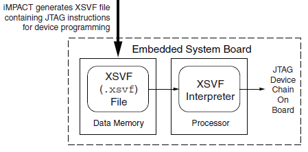
Floppy Emu has both a microcontroller and a CPLD working in tandem, and both must be programmed in order for the emulator to function. However, I don’t want to require two separate external programmers and the associated port connectors. My plan is to use a standard external ISP programmer for the microcontroller, but have the microcontroller program the CPLD, using the technique described in Xilinx app note XAPP058. The idea is to have the microcontroller act as an XSVF player, loading the CPLD configuration file from the SD memory card, and bit-banging the four JTAG pins on the CPLD to perform the programming.
This week, I finally got around to working on the XSVF player so I could program the CPLD on the Floppy Emu prototype board. The Xilinx player sample code is written in C, and was fairly easy to integrate into the emulator program. Using the functions I’d previously implemented, it was quick work to add an option to load a config file from the card and execute it with the XSVF player.
Predictably, once all the pieces were in place, it didn’t work. I spent a while checking and re-checking all my assumptions, reviewing the code, and writing debug info to the LCD, but made no progress. Finally I used the oscilloscope to peek at the JTAG signals, and discovered that they weren’t wiggling at all. All four JTAG signals were stuck high. I spent a few more hours chasing various theories why that might happen, and double-checked the electrical connectivity, before I gave up to do something else. Immediately after leaving the room, I suddenly realized what the problem was: in order to programmatically control the microcontroller JTAG pins, the JTAGEN fuse must be turned off, to disable hardware JTAG. Once I did that, the signals began wiggling as expected when I ran the XSVF player.
At this point the outgoing TMS, TCK, and TDI signals looked reasonable, but the JTAG communication still didn’t work. The error code from the player indicated that the TDO data returned from the CPLD didn’t match what was expected. Again the scope proved useful, this time by showing that TDO was stuck low, and never changed its value. No wonder the data didn’t match what was expected– it was always zero.
Here’s where I would normally describe how I finally solved the problem and got everything working, except this time I didn’t. At this moment TDO is still stuck low, and CPLD programming or other JTAG communication is not possible. I’ve examined the TMS, TCK, and TDI signals, and they look reasonable, and appear to roughly match the output of the PC-based XSVF player simulator that’s part of the Xilinx sample. So what might be wrong? Some theories, none of them great:
- The CPLD’s JTAG controller might not be active. But according to the datasheet, “If the device is in the erased state (before any user pattern is programmed), … the JTAG pins are enabled to allow the device to be programmed at any time. All devices are shipped in the erased state from the factory.”
- The JTAG controller might be in the wrong state to respond to the commands from the XSVF player. However, I looked at the code, and the first thing it does is reset the controller (by setting TMS high and pulsing TCK five times). This should be OK.
- The communication from the XSVF player might be garbled or broken. Maybe I accidentally swapped two signals, or introduced a bug in the player code? My preliminary scope debugging shows the signals look OK, so I’m skeptical this is the problem.
- The JTAG clock might be too fast. Initially the player code resulted in a JTAG clock rate around 500 kHz. I tried slowing it to under 1 KHz with no success.
- The player might not be waiting long enough for CPLD internal operations to complete. There’s a fairly long discussion of this in the sample code, and I’m fairly sure I did it correctly. When I tried slowing down the player even further, it didn’t help.
- The XSVF file might be bad. I’m using a file I generated with Xilinx iMPACT, which should simply query the device ID, then terminate.
- There might be an electrical short between TDO and ground. I’m fairly certain this isn’t the case, because before I disabled microcontroller’s JTAGEN fuse, TDO was about 4.5 volts. Now it’s zero. If there were a short to ground, it would have always been zero.
- The CPLD might be installed backwards or rotated, so the board trace isn’t actually connected to the TDO pin. I double-checked the orientation, and it looks correct.
- The CPLD might be damaged or defective.
For the moment at least, I’m stumped. I’m out of ideas for other things to try. I’m going to set this aside for a while, and hope that the solution will suddenly occur to me while I’m working on something else. Or failing that, I may at least come up with new theories that can be tested. Debugging electronics sure can be a pain!
8 commentsFloppy Emu, Large and In Charge
After months of procrastination, I finally assembled the Floppy Emu board and began work on the firmware modifications this week. So far, so good! Despite being out of practice with soldering, the assembly went smoothly, and the board checked out fine electrically. The firmware has now been partially converted to the new microcontroller and pin arrangement, and I’m able to read the SD card and write to the LCD screen without problems.
For those who may have missed the earlier progress updates, Floppy Emu is a floppy disk drive emulator for classic Macintosh computers like the Mac Plus. It plugs into the Mac’s DB-19 port, and behaves exactly like an external Sony 3.5″ disk drive would, so no special system software or other modifications are required. Floppy disk images are stored on a standard SD memory card, and a microcontroller (Atmel ATEMGA1284P) and CPLD (Xilinx XC9572XL) are used to read/write the floppy data. The data is converted into the GCR-encoded serial pulse stream that the Mac expects, exactly like the signal from a magnetic read head flying across a track on a real floppy disk.
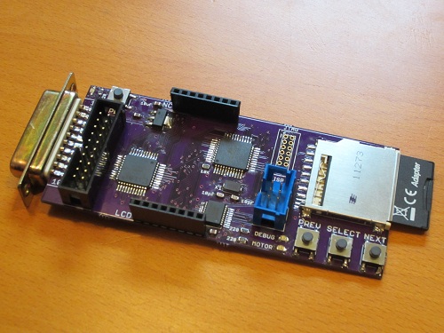
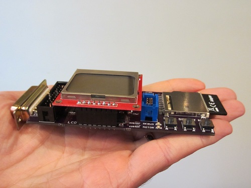
The Floppy Emu prototype was constructed on a breadboard, using whatever parts were on hand. The prototype demonstrated 100% successful read emulation of an 800K floppy disk, and partially successful write emulation, depending on the type of write operation and the specific SD memory card used. The new Floppy Emu board shown here uses a more powerful microcontroller and different type of CPLD, and combines everything onto a single custom-made circuit board that fits right into the back of the Mac at the external floppy port. Power is provided by the Mac too, so there’s nothing to do but connect it and go.
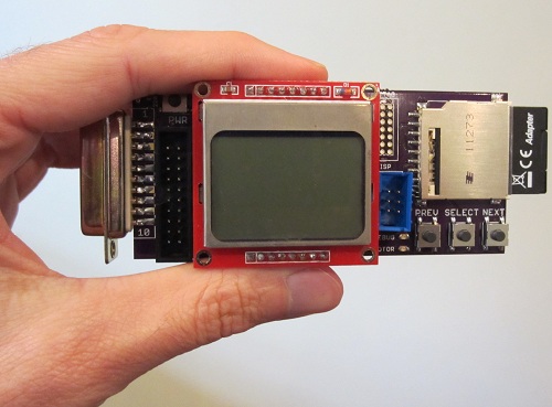
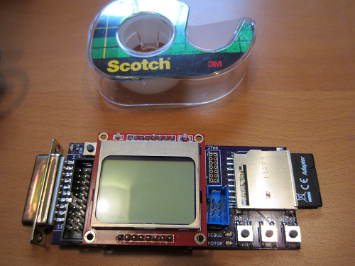
These photos show how small the Floppy Emu board is: about 1.75 inches wide and 4.5 inches long, including the DB-19 connector. The SD memory card extends an additional 0.5 inch beyond the end of the board. A roll of Scotch tape is also shown as a size reference. The Floppy Emu board is purple, but in most of the photos you’ll also see an LCD display on a red daughterboard. The LCD daughterboard is socketed, and can be connected and disconnected as needed. It’s the same Nokia 5110 LCD board sold by SparkFun and other several other vendors.
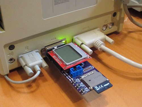
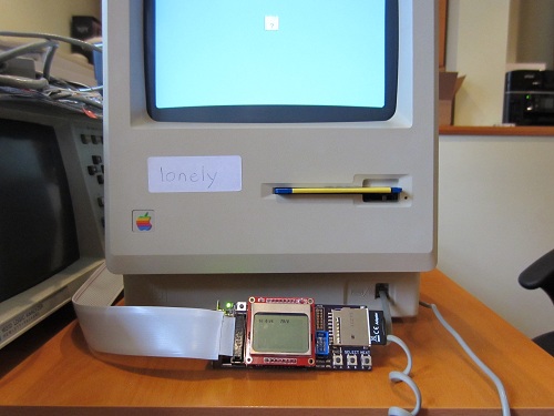
Thanks to its small size, the board fits nicely at the rear of the Mac, right between the mouse and the SCSI connector (or mouse and serial port on older Macs without SCSI).
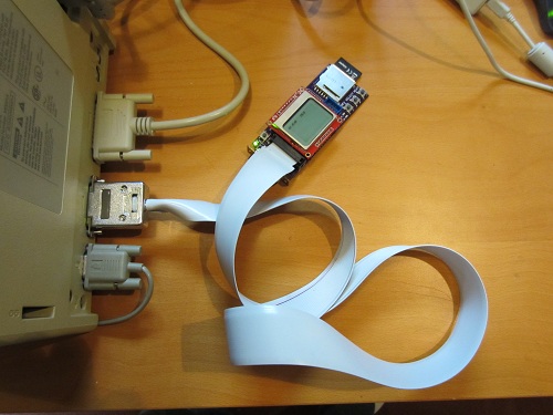
In addition to plugging straight into the external DB-19 floppy port, Floppy Emu can also be connected using a rectangular 20-pin IDC connector. This is the same connector found on the Mac motherboard, so a standard IDC cable can be used to connect Floppy Emu internally instead of at the external floppy connector. A DB-19 to IDC-20 adapter cable can also be used, such as the Apple II cable from IEC shown below. The cable enables Floppy Emu to connect to the external floppy port at the Mac’s rear, but positioned in the front of the Mac where it’s easier to use.
Everything is looking good so far. The next step is to program the CPLD, so communication with the Mac can be performed. The Floppy Emu board has a Xilinx JTAG connector at the upper-right of the LCD daughterboard, but it’s not populated and I’m hoping not to use it. Instead, my plan is save the CPLD configuration file on the SD memory card, and then use the microcontroller to configure the CPLD using a bit-bang JTAG method described in Xilinx app note XAPP058. Once that’s done, the final step will be to use the more powerful microcontroller on this board (as compared with the prototype) to experiment with new write emulation methods, and hopefully achieve 100% success for emulated floppy disk writes as well as reads.
13 comments