Amiga Serial Port
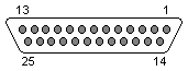 25 pin D-sub male
at the computer.
25 pin D-sub male
at the computer.
| Amiga 1000 only | Other Amiga models | |||
| 1 | GND | Frame Ground | GND | Frame Ground |
| 2 | TXD | Transmit Data | TXD | Transmit Data |
| 3 | RXD | Receive Data | RXD | Receive Data |
| 4 | RTS | Request To Send | RTS | Request To Send |
| 5 | CTS | Clear To Send | CTS | Clear To Send |
| 6 | DSR | Data Set Ready | DSR | Data Set Ready |
| 7 | GND | System Ground | GND | System Ground |
| 8 | CD | Carrier Detect | CD | Carrier Detect |
| 9 | n/c | +12Vdc | +12 Volt Power DC (20 mA) | |
| 10 | n/c | -12Vdc | -12 Volt Power DC (20 mA) | |
| 11 | n/c | AUDO | Audio out of Amiga | |
| 12 | n/c | n/c | ||
| 13 | n/c | n/c | ||
| 14 | -5Vdc | -5 Volt Power (50 mA) | n/c | |
| 15 | AUDO | Audio out of Amiga | n/c | |
| 16 | AUDI | Audio in to Amiga | n/c | |
| 17 | EB | Buffered Port Clock 716 kHz | n/c | |
| 18 | /INT2 | Interrupt line to Amiga | AUDI | Audio in to Amiga |
| 19 | n/c | n/c | ||
| 20 | DTR | Data Terminal Ready | DTR | Data Terminal Ready |
| 21 | +5Vdc | +5 Volt Power (100 mA) | n/c | |
| 22 | n/c | RI | Ring Indicator | |
| 23 | +12Vdc | +12 Volt Power (50 mA) | n/c | |
| 24 | /C2 | 3.58 MHz Clock | n/c | |
| 25 | /RESB | Buffered System Reset | n/c | |
| Name | Dir | Std | Notes |
| FGND | y | Frame ground - do not tie to signal ground | |
| TXD | O | y | Transmit data |
| RXD | I | y | Receive data |
| RTS | O | y | Request to send |
| CTS | I | y | Clear to send |
| DSR | I | y | Data set ready |
| GND | y | Signal ground - do not tie to frame ground | |
| CD | I | y | Carrier detect |
| -5Vdc | n | 50 mA maximum | |
| AUDO | O | n | Audio output from left (channels 0,3) port, intended to send audio to the modem |
| AUDI | I | n | Audio input to right (channels 1,2) port, intended to receive
audio from the modem; this input is mixed with the analog output the right. It is not digitized or used by the computer in any way. |
| DTR | O | y | Data terminal ready |
| RI | I | y | Ring indicator (A500/A2000) only shared with printer "select" signal |
| /RESB | O | n | Amiga system reset |
Warning: Pins on the RS-232 connector other than these standard ones described may be connected to power or other non-RS-232 standard signals. When making up RS-232 cables, connect only those pins actually used for a particular application. Avoid generic 25-connector "straight-thru" cables.
Source: Amiga Hardware Reference Manual
[Back]